Saturday, November 30, 2013

PiMAME - Retro Gaming on the Raspberry Pi


There have recently been a number of cool projects where the Raspberry Pi has been used to build a retro arcade cabinet. There is quite a bit of effort in fabricating a full arcade cabinet, but one can still enjoy the old arcade games just by connecting the Raspberry Pi to a TV and installing some software. One fairly complete software solution is PiMAME, which is a modified Raspbian built with all of the common emulators preinstalled. If you have ever attempted to compile just MAME on a Raspberry Pi, you can appreciate not having to burn those 6+ hours.

PiMAME - "PiMAME is the gaming OS for the Raspberry Pi. PiMAME runs MAME, Neo Geo, and PlayStation games out of the box, and is constantly being updated with new emulators and tools. Included is a suite of software designed to reduce the complexity and time needed to setup a fully working system. An updater is included with the distribution. PiMAME is based off of Raspbian, the official Linux distribution for the Raspberry Pi."

Emulators

PiMAME includes the following Arcade Emulators:
  • AdvanceMAME
  • Neo Geo (GNGeo)
  • MAME4All
  • FBA (CPS1, CPS2, Neo Geo)

PiMAME also includes the following Console Emulators:
  • PlayStation 1 (PCSX_ReARMed)
  • Genesis (DGen)
  • Nintendo Emulators
    • SNES (PiSNES / SNES9x Advmenu)
    • NES (AdvanceMESS)
    • Gameboy (Gearboy Advmenu)
    • Gameboy Advance (gpsp)
    • N64 WARNING ALPHA!
  • Atari 2600 (Stella)
  • Commodore 64 (VICE)

Installation

To enjoy PiMAME, one only needs to download the compressed image (1.6 GB), extract the image (4 GB), write the image to an SD card and power on the Pi (quickstart). I would highly recommend burning this image onto a secondary SD card, so as not to destroy your hard work on your current Pi setup. You really should have a couple of free SD cards laying around when playing with a Raspberry Pi.

Download and write the image to a SD card:
# wget http://sourceforge.net/projects/pimame/files/pimame-0.7.10.img.zip/download
# unzip pimame-0.7.10.img.zip
# sudo dd if=pimame-0.7.10.img of=/dev/sdh bs=1M

It took about 10-20 minutes to write the 4 GB image to my SD card. The /dev/sdh is where my USB SD Card Reader appared on my system. Check dmesg after connecting your USB SD Card Reader to determine the correct device node for your system.

Once the system boots, make sure to manually run raspi-config and use the common options such as "Expand Filesystem", "Change User Password", "Hostname", etc. The raspi-config tool is not auto run on boot like it is with the base Raspbian distribution.


PiMAME Menu

As you power on the Raspberry Pi if you see the PiMAME logo (pictured above) you know you burned the right image. Once the PiMAME has fully booted, you will be presented with the following menu:

From this menu you can start the various game emulators.  You can also start some maintenance operations (under Tools) such as raspi-config, reboot and shutdown.  Unfortunately, the system update is not included in this menu.

If you happen to exit the PiMAME Menu, you can return to it by running:
# python /home/pi/pimame_files/menu.py

Add ROMs Through Web Interface

The PiMAME comes with a convenient built in web server that can be used to add ROMS. There is also a built in FTP server (recommended for files over 50 MB), for whichever is more convenient.

NOTE: All ROMs should be stored in the /home/pi/roms/ directory

To determine your IP address, you simply select "Tools" from the menu. Your IP address will be listed at the top of the "Tools" page.

Once you have the IP address, open up a browser and browse to the IP address.


Click the "ROM Uploader" button, and login. Select the "roms" folder. This is where your ROMs should go.
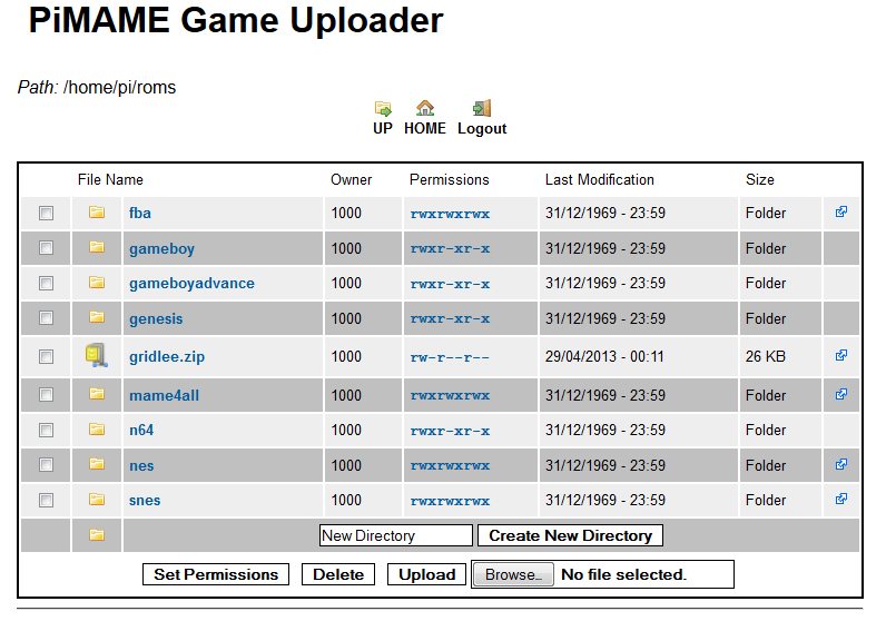
ROMs

PiMAME only comes with one freeware ROM by the name of 'Gridlee'.

So where does one get other game ROMs from?

Legal:
Less Legal: ("Yo Ho, Yo Ho, A Pirate's Life For Me")
Just in case you are curious, there is a very small handful of game creators that have opted to allow legal usage of their game ROMs.  Unfortunately, none of these are any of the big game developers like Nintendo, who are very actively against emulators and ROMs.

Gridlee

Let's see one of the emulators in action.  As Gridlee is the only included ROM, let's play Gridlee.  To start Gridlee, from the PiMAME menu, select "Arcade Emulators" then "AdvanceMAME".  When AdvanceMAME loads there will be only one game listed, Gridlee.  Press enter to start Gridlee.

The point of Gridlee is to move your character around and catch the bouncing balls.  There are also tall cylindrical enemies you can shoot, before they electrify the ground and hurt you.

I was a bit frustrated at first, trying to determine what they key bindings were and how to start the game.  To save you a few seconds, press "1" to start a single player game, or press "2" for a one-at-a-time two player game.  Press "5" to add coins for player 1 and press "6" to add coins for player 2.  The arrow keys will move your character around, and the "Control" key will fire your weapon.  You can press "F1" to see a list of the key options.

Maintenance

To perform updates and other tasks, I prefer to do these from a remote SSH session. As mentioned before, to determine your IP address, you can simply select "Tools" from the menu, or you can exit the PiMAME Menu and run ifconfig. Your IP address will be listed at the top of the "Tools" page.

The default user login is user "pi" with a password of "raspberry". When you connect through SSH the PiMAME menu will appear. This is due to PiMAME being set to start in the user's profile. None of the applications will run from a SSH session, so select menu option "6 - Exit" to return to the console.

Once you are in the shell, you can run the PiMAME update (or other console tasks).
# cd pimame_installer/
# sudo ./update.sh

# sudo reboot


Friday, November 29, 2013

Raspbian Wireless Wi-Fi


Are you wanting to connect to your Raspberry Pi over WiFi?  The following are instructions for configuring WiFi on Raspbian (the other Debian based Raspberry Pi distributions should work in a similar manner).

Although the Raspberry Pi model B conveniently comes with an Ethernet port (the model A does not), there are a number of applications where having WiFi is super convenient.  I have one of my Raspberry Pi out in our garage, controlling and monitoring the garage door.  Running a network cable would have been a very ugly solution.

To connect via wireless one must add a WiFi USB dongle, which will consume one of your precious few available USB ports (maybe time to expand with a powered USB hub).  There are other low level hardware options, but nothing quite as simple, and plug and play, as a WiFi USB dongle.

There are a number of compatible WiFi USB dongles on the market.  Review the RPi USB Wi-Fi Adapters list for verified adapters.  My personal favorite is the Edimax EW-7811Un 150 Mbps Wireless 11n Nano Size USB Adapter (pictured above), as it is popular, works fairly well, and is only $9 on Amazon (with Amazon Prime).

To enable WiFi, simple connect your WiFI USB dongle to an available USB port, modify your network interfaces configuration file and restart your Pi.  To configure the network interfaces configuration file, add the wlan0 section to /etc/network/interfaces:
auto lo
iface lo inet loopback

iface eth0 inet dhcp

auto wlan0
allow-hotplug wlan0
iface wlan0 inet dhcp
        wpa-ssid "YOUR_SSID"
        wpa-psk "YOUR_WEP_OR_WPA_KEY"
wpa-conf /etc/wpa_supplicant/wpa_supplicant.conf

iface default inet dhcp

Your WPA key above can specified as either be the clear text passphrase, or the hex encoded version.  If you would prefer to not list your clear text passphrase you can generate the encoded hex version with the wpa_passphrase tool or even online tools.
# wpa_passphrase test testtesttest
network={
        ssid="test"
        #psk="testtesttest"
        psk=b6df3a2ab8a19db1b646e4a852892d39fc4e73c13cb2ade0ad9d8887bb414ecd
}

WPA passwords are managed on Linux with the wpa_supplicant tools.  The wpa_passphrase tool is designed to generate a section that can be added to the /etc/wpa_supplicant/wpa_supplicant.conf configuration file.  You can also add multiple SSIDs to wpa_supplicant.conf.  If you have multiple SSID you may want to connect to (such as a mobile Raspberry Pi), don't add the wpa-ssid and wpa-psk lines to the interfaces file.  Instead use the wpa_passphrase tool to add multiple sections to the wpa_supplicant.conf configuration file.

You can auto add the output of wpa_passphrase, to the wpa_supplicant.conf, with the following:
# wpa_passphrase test testtesttest >> /etc/wpa_supplicant/wpa_supplicant.conf

Finally, to bring up the wireless, either reboot the Raspberry Pi, or run the following:
# ifdown wlan0
# ifup wlan0

You should now be able to use your Raspberry Pi over WiFi.


For reference, there are several command line tools that can be used to manually configure and view wireless settings.

To see your wireless IP address:
# ifconfig wlan0
lan0     Link encap:Ethernet  HWaddr 80:1f:02:be:XX:Xx
          inet addr:10.10.10.100  Bcast:10.10.10.255  Mask:255.255.255.0

To manually configure SSID and other wireless options, the iwconfig command can be used. The output of iwconfig looks similar to the ifwconfig, but with wireless settings:
# iwconfig wlan0
wlan0     IEEE 802.11bg  ESSID:"MY_SSID"  Nickname:""
          Mode:Managed  Frequency:2.437 GHz  Access Point: 00:14:BF:E0:XX:XX
          Bit Rate:54 Mb/s   Sensitivity:0/0
          Encryption key:****-****-****-****-****-****-****-****   Security mode:open

To scan for wireless access points:
# iwlist wlan0 scan
wlan0     Scan completed :
          Cell 01 - Address: 00:14:BF:E0:89:XX
                    ESSID:"MY_SSID"
                    Protocol:IEEE 802.11bg
                    Mode:Master
                    Frequency:2.437 GHz (Channel 6)
                    Encryption key:on
                    Bit Rates:54 Mb/s


Wednesday, November 27, 2013

Raspbian Installation


The Raspberry Pi is a great little device that can be used for hardware hacking, environment monitoring, electrical engineering, media center and anything else one can imagine.  But, the Raspberry Pi does not come with an Operating System.  So first things first, we need to install one.  The absolute most popular distribution is Raspbian, based on Debian Wheezy.

Write Image

Raspbian comes as a disk image, which needs to be downloaded and written to a SD card.  The SD card needs to be at least 4 GB and at least a class 4 (speed).  The SD card will then be inserted into the Raspberry Pi and finally powered on.  I will be using Linux to write the disk image to the SD card.  If you are using Windows, you can use the "Win32DiskImager" tool (See Connecting to the Pi).


The following will download Raspbian and write it to the SD card.  At the time of this writing, the latest version of Raspian is 2013-09-25-wheezy-raspbian.zip.  Adjust the file name if latest has changed.  The disk image is about 600 MB so be patient as it downloads.  Writing a 600 MB image to an SD card is also slow (about 7 minutes), so additional patience will be needed here as well.

# wget http://downloads.raspberrypi.org/raspbian_latest
# unzip 2013-09-25-wheezy-raspbian.zip
# sudo dd if=2013-09-25-wheezy-raspbian.img of=/dev/sdh bs=1M

The /dev/sdh is the device node my USB SD card reader/writer appeared as.  I used dmesg, after connecting the USB device, to determine this.

Now that we have the image written to the SD card, we can plug it into the Raspberry Pi and power it on.  To make life easier one should connect an HDMI (or RCA video) to both the Raspberry Pi and a TV, connect a USB keyboard and mouse (optional), connect network via Ethernet (optional), connect finally connect power through a USB Micro cable.  The Raspberry Pi will now begin to boot, and you should see the boot process, with a little raspberry image logo, on your TV.

raspi-config

On the first boot, you will be presented with the text dialog based raspi-config tool.


This tool can be used to configure a variety of features, but for now it is important to just "Expand Filesystem".  This will take our 600 MB image and expand it out to the full size of our SD card, which can vary in size.

The other 3 options I like to change at this point are User Password, Boot to Desktop, Time Zone (found under Internationalization Options), Hostname (under Advanced Options), and Memory Split.

If you would like to announce to the world your usage of the Raspberry Pi, select the Add to Rastrack option, which will add this Pi to the online Raspberry Pi Map.  Others can then see your Pi on the Rastrack map.

If you need to modify these configurations at a later time, the raspi-config tool can be rerun with:

# sudo raspi-config

The raspi-config tool can also be run over SSH, if that is more convenient.

Once you are happy with your changes, quit out of raspi-config.  It will ask if you would like to reboot, if needed, and you should.

Desktop vs Headless

There are two modes the Raspberry Pi is commonly run in: desktop and headless.  Raspbian defaults to booting to headless mode.

With desktop, one is interested in interacting with the Pi through a GUI with mouse and keyboard.  Within raspi-config, you will want to set the "Boot to Desktop" option and also modify the "Memory Split" to the 64 MB default, or higher.  The "Memory Split" determines how much memory is allocated to the GPU.

With headless, (Raspian's default) one is interested in interacting remotely with the Pi through SSH or a web interface.  You will want to set the "Boot to Console" option and drop the "Memory Split" to a minimal 16 MB.

Default Login

Raspbian is setup with a default user by the name of "pi".  The default password for user pi is "raspberry", unless this was changed within raspi-config.


Networking

The Raspberry Pi is far more useful with network access.  Simply connect an Ethernet cable to Raspberry Pi and it should acquire an IP address on boot.  To determine your IP address, run the "ifconfig" command.

# sudo ifconfig
eth0      Link encap:Ethernet  HWaddr b8:27:eb:28:ea:55
          inet addr:10.10.10.47  Bcast:10.10.10.255  Mask:255.255.255.0
          UP BROADCAST RUNNING MULTICAST  MTU:1500  Metric:1
...

With the IP address, you can now connect to the Raspberry Pi over SSH, which opens a world of possibilities.

Wireless access is also possible, but you will need to purchase a WiFi dongle and modify some configuration files.

System Update

Lastly, there are constantly changes being made to the packages installed.  Raspbian (Debian based) uses APT for package management.  To keep your system updated, you should occasionally run the following commands:

# sudo apt-get update
# sudo apt-get upgrade
# sudo apt-get dist-upgrade  # (optional)

APT Package Management

A quick overview of APT package management... (I use the package "screen", a terminal multiplexer, in this example

To install a package: (apt-get install [package])

# apt-get install screen

To uninstall a package: (apt-get remove [package])

# apt-get remove screen

To search for a package: (apt-cache search [package])

# apt-cache search screen

To see package informaiton: (apt-cache show [package])

# apt-cache show screen


RaspBMC Media Center Installation


The Raspberry Pi can be used as a media center.  The Raspberry Pi media center can serve up media such as music, videos and pictures.  There are a number of distribution options based on XBMC the "Open Source Home Theatre Software".  The two most popular are RaspBMC and OpenELEC.  The following is a quick guide for installing RaspBMC.

Write Image


First, download latest RaspBMC image and write to SD card:
# wget http://downloads.raspberrypi.org/raspbmc_latest
# gzip -d raspbmc-2013-10-02.img.gz
# sudo dd if=raspbmc-2013-10-02.img of=/dev/sdh bs=1M

I used Linux to write the image to the SD card.  If you are using windows, you can use the "Win32DiskImager" tool (See Connecting to the Pi).  The raspbmc-2013-10-02.img.gz was the available version at the time of this post, adjust the file name as needed.  The /dev/sdh is the device node my USB SD card reader appeared as.  I used dmesg, after connecting the USB device, to determine this.

First Boot

Connect an HDMI cable to both the Raspberry Pi and a TV.  If you are planning to serve media files up from another server (across NFS / CIFS), connect a network cable.  Although it is possible to use wireless, it is recommended to use at least a Fast Ethernet wired cable, otherwise the video performance may suffer.  Connect power, and watch the Raspberry Pi boot.

On the first boot, you will be asked to configure a few of options, such as locale and time, within a text based dialog wizard.  The configuration options are minimal compared to Raspbian's raspi-config.  The Raspberry Pi will reboot again, this time into RaspBMC windows manager (pictured above).

You are now ready to start using the RaspBMC Media Center.

Serving Media from USB

The quickest way to play media is to copy the media files to a USB drive, and connect this to the Raspberry PI.  From here, it is just a matter of browsing to the files you wish to play.

Service Network Media over NFS

If you are like me, you have a massive file server in the basement housing your collection of music, videos and photos.  To remotely gain access to these files, we can mount an NFS (or CIFS) share.

The NFS tools are already available, but to mount an NFS share we need to first enable the RPC Binding service.
sudo service rpcbind restart
sudo update-rc.d rpcbind defaults

Next we can  mount our NFS share:
sudo mkdir /pub
sudo mount myserver:/pub /pub

Adjust "myserver" and "/pub" to match your server name and NFS share.

To make this available on boot, add the following to /etc/fstab:
myserver:/pub      /pub            nfs     defaults        0 0

Now you will have full access to your media from your Raspberry Pi.

DVD Playback

The Raspberry Pi can also playback MPEG encoded videos, but first you will need to purchase a MPEG-2 license from RaspberryPi.com for about $4.  After waiting about 72 hours for your license key to arrive by email you can then add your license key to /boot/config.txt.  Now you will be able to play your MPEG encoded videos through RaspBMC.


Sunday, October 6, 2013

Garage Door Part 2 - Monitor Door (GPIO Input)

Project Garage Door
Now that I can trigger our garage door, I needed a way to determine if the garage door is open or closed.  I purchased a Magnetic Reed Switch (commonly used for windows Theft Deterrence) to detect this change.
Magnetic Reed Switch
The way a reed switch works is as the magnetic block nears the switch block, the sensitive switch is pulled closed, and the circuit will be completed.

This particular magnetic switch is really nice, as it includes terminals for both Normally Closed (NC) and Normally Opened (NO), depending on your needs.  Most cheaper reed switches only include a Normally Opened option.  For my setup I choose to use the Normally Opened (NO), so the triggered switch would close the circuit loop.  Either configuration could be used, and would just need to be adjusted in the code logic.  This magnetic switch also includes the option of being taped (included) or screwed/nailed to a surface.

I ran a couple of tests with the switch and Raspberry Pi, to make sure the switch would work as expected, and the code would detect the changes.  Once I was satisfied with the results, it was time to mount the components to their final resting places.

I tried finding a position on the wall that I could mount the magnetic switch, but no position appeared to get close enough to the door, but yet far enough away to not get stuck.  I finally settled on attaching the switch block to the garage floor and the magnetic block to the bottom of the garage door, within the groove.  I found that the door does not actually touch the ground as there is weather stripping in the way, which gave excellent clearance for the switch.

Magnetic switch - switch block
Magnetic switch - magnetic block


Then I ran a pair of 20 gauge "bell" wires from the magnetic switch, up the wall, across the ceiling and down to my Raspberry Pi.  I left a bit of slack on each end, just in case I need to make adjustments in the future.  To keep the wires from falling, I used a simple stapler, as the wires were very light weight.  The Raspberry Pi, breadboard, and USB Hub are all bundled within the plastic blue box, to keep the dust (and cat) away.
Wires running to Raspberry Pi

Wires running along the ceiling


To finish the circuit I then needed to connect the switch to power, ground and GPIO pins.  The following schematic is the recommended circuits for a simple switch input circuit, and includes Pull Up and Pull Down resistor configurations.  The most commonly used layout is the Pull Up resistor so this is what I will use for my circuit (either could be used).  (Please read Pull-up Resistor for more information, if curious)
GPIO Input Circuits with both Pull Up (top) and Pull Down (bottom) configurations
 
My "Pull Up" input circuit that matches the above schematic

The whole bundled mess, found within the protective plastic box:


Raspberry Pi, breadboard and USB Hub within protective plastic box
I use the following Python code, running on the Raspberry Pi to test and report if the switch is opened or closed.  This code is the foundation for a much larger bit of code used for monitoring, opening and closing the garage door.
#!/usr/bin/env python

import sys
import time

import RPi.GPIO as GPIO

pin = 25

GPIO.setmode(GPIO.BCM)
GPIO.setup(pin, GPIO.IN)

try:
  while True:
    input_value = GPIO.input(pin)
    if input_value:
      sys.stdout.write('-')
    else:
      sys.stdout.write('.')
    sys.stdout.flush()
    time.sleep(.01)
finally:
  GPIO.cleanup()

Next, we will look at a simple web interface to control the garage door: Garage Door Part 3 - Web Interface


Pull-up Resistor

What is a Pull-up Resistor?

Imagine the following simple circuit:

Simple "floating" switch circuit
When the switch is closed there is a complete circuit from GPIO pin to ground.  A reading of the GPIO pin will read "low".

What happens when the switch is opened, though?  This leaves the GPIO pin in a "floating" state which is unable to determine a "high" or "low" state.  If you now read the GPIO pin, it will randomly report high and low states.

To force the GPIO pin to a "high" state, when the switch is open, we can add a very high Ohm resistor to the circuit and to the voltage source.
Simple switch circuit with Pull Up resistor

As the resistor is so high, when the switch is closed the resistor does not directly affect the rest of the circuit.  But when the switch is opened, the high resistance is better than no path and will "Pull Up" the circuit path to the voltage source, so the GPIO pin will now detect a "high" state.

Depending on if you want the opened switch circuit to be pulled up to the voltage source, or pulled down to the ground, different circuits can be built:
Input Circuits with "Pull Up" (top) and "Pull Down" (bottom) configurations

"Pull-up resistors are used in electronic logic circuits to ensure that inputs to logic systems settle at expected logic levels if external devices are disconnected or high-impedance is introduced. When the switch is open the voltage of the gate input is pulled up to the level of Vin. When the switch is closed, the input voltage at the gate goes to ground.  A pull-up resistor weakly "pulls" the voltage of the wire it is connected to towards its voltage source level when the other components on the line are inactive. A pull-down resistor works in the same way but is connected to ground." (source)