Sunday, December 22, 2013

TEMPer USB Thermometer on Raspberry Pi

TEMPer USB Thermometer
For a fairly cheap solution, nothing quite compares in price and convenience to the TEMPer USB Thermometer.  Due to their low price point, I have used several of these as secondary temperature check points in a server rack before.  They can be picked up for about $15 to $22 on Amazon, or cheaper on eBay.  The TEMPer is not as accurate, or reliable, as something like the Temperature@lert, which runs for about $130, but for general temperature estimation they work sufficient for my needs.

I found the easiest way to use the TEMPer with Python is to install the pyusb library and a simple temper Python class written by Bill Mania.  There were a few small issues that I ran into with the original code, so I forked the code on Github and posted the changes as the PyTEMPer repo seen below.

First let's make sure Linux can see your TEMPer device. We are looking for devices that have the VendorID of 1130 and DeviceID of 660c.
# lsusb | grep 1130:660c
Bus 004 Device 002: ID 1130:660c Tenx Technology, Inc. Foot Pedal/Thermometer

If your device is not found, the PyTEMPer script will not work with your device.

PyTEMPer Installation:
# cd /opt

# ## forked from http://www.manialabs.us/downloads/Temper.py
# sudo git clone https://github.com/kiloforce/PyTEMPer
# cd PyTEMPer

# ## Get PyUSB (if you do not already have installed)
# sudo git clone https://github.com/walac/pyusb
# sudo ln -s pyusb/usb usb

# ## Get sample temperature to verify code is setup correctly
# sudo python temper.py
0:2, 22.56 Celsius / 72.61 Fahrenheit

Now that we have the PyTEMPer class working, we can build the following Python script to get the current temperature repeatedly:
import sys
import time

sys.path.append('/opt/PyTEMPer')
import temper
temp = temper.Temper()

if not temp.devices:
    print "Error: not TEMPer devices found!"
    sys.exit(1)
device = temp.devices[0]

while True:
    # get temperature
    tempc = temp.getTemperature(device)
    print "Celsius: " + str(tempc)

    # only check temperatures every 10 seconds
    time.sleep(10)

In the final lala-pi TEMPer code, I included code to demonize the process, syslog for logging, and ZeroMQ messaging.  If you are interested in the full lala-pi source code (still a work in progress), this can be found in the GitHub lala-pi repo on Bitbucket.
# git clone https://github.com/oeey/lala-pi

More to come...   see label: lala-pi

USB Keyboard on Raspberry Pi

Targus Numeric Keypad

For the lala-pi "room security system" project I am building, I needed a way for an intruder to enter in a security code to disable the security system.  A full keyboard is a bit too bulky.  Luckily, small USB numeric "Ten Key" keypads are common, and fairly cheap.  I am sure their primary market is for accountants, but I purchased one to accompany my small laptop keyboard, some years ago.

Targus keypad model

I connected the keypad to the Raspberry Pi, and immediately noticed the first roadblock.  The keypad sends key presses to the system console, not to the SSH session I use to manage the Pi.  As this Pi will be headless, I needed to find a way to capture input from the keypad.

Fortunately for me, there is already a Python project called "evdev" that:
"provides bindings to the generic input event interface in Linux. The evdev interface serves the purpose of passing events generated in the kernel directly to userspace through character devices that are typically located in /dev/input/"
Score!

This solution would work equally well with a keypad or a full-sized keyboard.  The only difficult problem was determining which /dev/input/ device to use.  This particular keypad appeared as "/dev/input/by-id/usb-ORTEK_USB_Keyboard_Hub-event-kbd".  Your's may appear differently.

Here is the first bit of code I used to test the keypad, which worked quite well:
#!/usr/bin/env python

import string
import os
import sys
import time

# pip install evdev
from evdev import InputDevice
from select import select

# look for a /dev/input/by-id/usb...kbd or something similar
DEVICE = "/dev/input/by-id/usb-ORTEK_USB_Keyboard_Hub-event-kbd"

dev = InputDevice(DEVICE)

while True:

    # wait for keypad command
    r, w, x = select([dev], [], [])

    # read keypad        
    for event in dev.read():
        if event.type==1 and event.value==1:
            if event.code in keys:
                print "KEY CODE: " + event.code
                # do something with this key press
                # ...

In the final lala-pi keypad code, I included code to demonize the process, key-code to key-name mappings, syslog for logging, and ZeroMQ messaging.  If you are interested in the full lala-pi source code (still a work in progress), I setup a GitHub lala-pi repo.
# git clone https://github.com/oeey/lala-pi.git

For reference, this is the keycode to key name mapping I use:
# keymapping determined by trial and error
keys = {
 79: "1",
 80: "2",
 81: "3",
 75: "4",
 76: "5",
 77: "6",
 71: "7",
 72: "8",
 73: "9",
 82: "0",
 83: ".",
 28: "ENTER",
 78: "+",
 74: "-",
 14: "BS",
 55: "*",
 98: "/",
 # Numlock keys:
 111: "N.",
 110: "N0",
 107: "N1",
 108: "N2",
 109: "N3",
 105: "N4",
 # notice the missing N5
 106: "N6",
 102: "N7",
 103: "N8",
 104: "N9",
}

More to come...   see label: lala-pi

Saturday, December 21, 2013

ZMQ Messaging System - lala-pi

ZeroMQ Messaging Service
The first hurdle I ran into with this over-engineered room security system, was the complexity of the monolithic application, I was putting together, to control the various sensors and devices.  Luckily, a coworker suggested I break the system up into smaller components and use a messaging system.  This is a common practice for enterprise level applications.

Message-oriented middleware (MOM)

For reference: "Message-oriented middleware (MOM) is software or hardware infrastructure supporting sending and receiving messages between distributed systems. MOM allows application modules to be distributed over heterogeneous platforms and reduces the complexity of developing applications that span multiple operating systems and network protocols. The middleware creates a distributed communications layer that insulates the application developer from the details of the various operating systems and network interfaces." (ref)

That is a fancy way of saying that instead of a monolithic application, smaller self contained applications send messages and requests between each other.  This allows individual components to be maintained individually, and also allows one to potentially duplicate components for distributed load balancing.

Would my little security system become more complex, or simplified by adding a messaging system?  I determined that the education alone would be worth it, so I jumped onto the messaging system bandwagon.

Messaging System Options

I researched several messaging system options, with my primary requirements being:

  • Compatibility with the Raspberry Pi
  • Compatibility with Python
  • Low memory footprint
  • Fast performance
After investigating popular options such as ActiveMQ and RabbitMQ, I settled on a tiny messaging system called ZeroMQ.

ZeroMQ

ZeroMQ (also ØMQ or ZMQ) is a minimal Message-oriented middleware (MOM).  It is only a small step above just using bare TCP sockets, but provides enough messaging power to do pretty much anything you could want.

The first benefit of ZeroMQ is it takes the TCP socket stream and breaks it down into the individual messages for me.  I then don't have to worry if the partial data stream I receive is complete or not.  With ZeroMQ you receive the whole message, or not.  Messages are all "string" based, which makes them easy for Programming languages like Python to handle.  If you need to send non-string messages, you will need to decode them from the received string, or play with the optional RAW messaging functions.

The second benefit of ZeroMQ is it handles connections for me.  I don't have to worry about if a connection is lost, as it will reconnect for me, when able to.  I also don't have to worry about if a server doesn't exist at the time a client connects, as ZeroMQ will auto connect to the server when the server eventually comes online.

The third benefit of ZeroMQ is it handles distributed messages out of the box.  I can send a single message to my publishing pipe, and any clients that are subscribed to that pipe will receive the message.

ZMQ Patterns

According to the ZeroMQ documentation, the following messaging patterns are baked into it's core:
  • Request-reply, which connects a set of clients to a set of services. This is a remote procedure call and task distribution pattern.
  • Pub-sub, which connects a set of publishers to a set of subscribers. This is a data distribution pattern.
  • Pipeline, which connects nodes in a fan-out/fan-in pattern that can have multiple steps and loops. This is a parallel task distribution and collection pattern.
  • Exclusive pair, which connects two sockets exclusively. This is a pattern for connecting two threads in a process, not to be confused with "normal" pairs of sockets.
The pattern I have chosen to use for my room security system is the Publisher-Subscriber model, with a message router in the middle that will replay all messages to every other application in the system.  Applications can then choose which messages to subscribe to (or even all of them), and which to ignore.

For example, my keypad application will be waiting for a key press.  When a key is pressed, such as the "LEFT" key, it will generate a "KEY: LEFT" message and send it to the message router.  The message router will then turn around and replay the "KEY: LEFT" to any application that is subscribed to messages prefixed with "KEY:".  The music player application, which is listening for "KEY:" will then pick up the message and take the predetermined action, such as going to the previous song.

Another fascinating side effect from this setup is I could generate a "KEY: LEFT" message from any application, such as a web interface, or even a cell phone app.  Security issues aside, think of the possibilities.  I know, this blew my mind too!

Installation

There are two parts to get ZeroMQ installed and working with Python.  First, you need the system libraries, and second the Python bindings.

System Libraries:
# For Raspbian:
apt-get install python-zmq

Python Binding:
easy_install pyzmq
# or
pip install pyzmq

Source Code

If you are interested in the full code (still a work in progress), see the lala-pi repo on GitHub.
# git clone https://github.com/oeey/lala-pi.git

Message Router

As ZeroMQ is a minimal messaging system, you are left on your own to build the messaging router services.  Thankfully this is quite simple.

Here is the minimal message router I started with:
#!/usr/bin/env python

import os
import sys
import time

import zmq

# ZMQ context, only need one per application
context = zmq.Context()

# for sending messages
z_send = context.socket(zmq.PUB)
z_send.bind("tcp://*:5555")

# for receiving messages
z_recv = context.socket(zmq.SUB)
z_recv.bind("tcp://*:5556")
z_recv.setsockopt(zmq.SUBSCRIBE, '')  # subscribe to everything

print "ZMQ server started."
while True:
    message = None

    # wait for incoming message
    try:
        message = z_recv.recv()
    except zmq.ZMQError as err:
        print "Receive error: " + str(err)

    # replay message to all subscribers
    if message:
        try:
            z_send.send(message)
        except zmq.ZMQError as err:
            print "Send error: " + str(err)

I then added some logging of the messages, and a bit of clean up code for a more robust message router:
#!/usr/bin/env python

import os
import sys
import time

import zmq

# ZMQ context, only need one per application
context = zmq.Context()

# for sending messages
z_send = context.socket(zmq.PUB)
z_send.bind("tcp://*:5555")

# for receiving messages
z_recv = context.socket(zmq.SUB)
z_recv.bind("tcp://*:5556")
z_recv.setsockopt(zmq.SUBSCRIBE, '')  # subscribe to everything

# record all message requests to a file
record = open('router-records.txt', 'w')

# counters for messages
last_time = time.time()
count = 0

print "ZMQ server started."
while True:
    message = None

    # wait for incoming message
    try:
        message = z_recv.recv()
    except zmq.ZMQError as err:
        print "Receive error: " + str(err)

    # if message received, and not an error, then
    # replay message to subscribers
    if message:
        count += 1
        record.write(str(count) + ':' + message + '\n')
        
        # occasionally flush the router-record.txt file
        if time.time() > last_time + 2:
            record.flush()
            last_time = time.time()

        try:
            z_send.send(message)
        except zmq.ZMQError as err:
            print "Send error: " + str(err)

        if message.strip() == "DEATH":
            print "Death received, shutting down."
            break


print "Shutting down..."
record.close()
z_send.close()
z_recv.close()
context.term()
print "Shut down."

My final version also includes some "forking" code to daemonize (background) the application. As print statements would be lost to the void, I also converted all of the print statements over to using syslog.  The full source can be found in the Bitbucket repo.

Now, with a working router, I can build any application, connect to the message router and have a fully functional messaging system.

Message Client

For a sample messaging client, here is my "test" client that I use. Using this as a template, a full application could be constructed
#!/usr/bin/env python

import os
import sys
import time

import zmq

context = zmq.Context()

z_recv = context.socket(zmq.SUB)
z_recv.connect("tcp://localhost:5555")

z_send = context.socket(zmq.PUB)
z_send.connect("tcp://localhost:5556")
# z_recv.setsockopt(zmq.SUBSCRIBE, 'KEYBOARD:')
z_recv.setsockopt(zmq.SUBSCRIBE, '')  # subscribe to everything

print "ZMQ Client Started!"

while True:
    sys.stdout.write("Message: ")
    message = raw_input().strip()

    if message:
        try:
            print 'SEND:' + message
            z_send.send(message)
        except zmq.ZMQError as err:
            print 'Send error: ' + str(err)

    try:
        # don't block if no message waiting
        in_message = z_recv.recv(zmq.DONTWAIT)
        print 'RECV:' + in_message
    except zmq.ZMQError as err:
        print 'Receive error: ' + str(err)


More to come...   see label: lala-pi

Room Security System - lala-pi

Concept design of room security system

My daughter asked if I could build a security system for her room.  Her brother tends to sneak in and play with her makeup and stuff.  I thought about it for a few minutes, and my mind started racing with fantastic ideas.  Challenge accepted!  And just like an engineer, I way over engineered this project.  I am calling this project lala-pi in honor of my daughter's nickname.

Of course the whole thing is being built around a Raspberry Pi.  I already have several of the components up and working.

The way this security system will work is when an intruder enters the door, it will trigger the magnetic reed sensors attached to the door.  This in turn will trigger a GPIO pin on the Raspberry Pi.  The Raspberry Pi will respond by taking a picture through the web camera, and generate an audible warning through the speakers.  The Pi will then give the intruder a few seconds to approach the attached USB keypad, enter in the security code and disable the security alarm.

If they fail to enter in the security code, the system will then trigger a full scale assault, including sirens through the speakers, additional photos for evidence, and a notification sent to cell phones.  (Do you thinking electric shock panels embedded into the floor are a good idea, or have I been playing too much Tomb Raider?)

But why stop there?  With wireless access, a keypad, speakers and Pandora, I am going to also turn this into a internet music player.  And with access to Google Calenders, I am going to include an optional musical alarm clock feature.  Just for good measure, I am throwing in a temperature sensor, motion detector and extra USB storage.  If I get really ambitious, I would like to include some power control switches and have the lights go/off based on motion detection.

I know what you are thinking, I should round things off by embedding a large red circle light on the wall, and calling it Hal.
Hal 9000 - "I'm sorry Dave, I'm afraid I can't do that"

If you are interested in the final full code (still a work in progress), I setup a project (lala-pi repo) on GitHub.
# git clone https://github.com/oeey/lala-pi.git

More to come...   see label: lala-pi


Sunday, December 15, 2013

Raspberry Pi with Arduino Slave

The power of the Raspberry Pi is incredible, but amazingly there are tasks which it is not fully equipped to handle.  Such items are 5V Logic (for certain chip sets and controllers), Analog I/O (for variable level sensors) and Real Time operations (for motor controllers).

Arduino Uno

A common solution is to attach another micro-controller board such an Arduino.  The Arduino is a versatile micro-controller that comes in a variety of sizes and packages with "Shields" for advanced expansion.  The most common version is the Arduino Uno (pictured below).

Arduino Uno Packaging
Arduino Uno fits in the palm of your hand
There are several methods to communicate with an Arduino from the Raspberry Pi. Serial, I2C and GPIO are common methods.  The method I prefer is to communicate over Serial, through the USB port, that I program and power the Arduino with (not to be confused with Serial through the serial pins on both boards).

To connect the Arduino Uno, using a USB cable (USB type B to A cable) I connected it to a powered USB hub.  Then I connected the USB hub to my Raspberry Pi.  If your power adapter is sufficient amperage, you should be able to connect the Arduino directly to the Raspberry Pi.  I will have several other USB device attached, so the USB powered hub works best for me.

Arduino Uno connected to USB
connected to Raspberry Pi
Arduino Uno close up

Arduino IDE

Now that the Arduino is attached to the Raspberry Pi, we can program the Arduino using the Arduino IDE.  This can be installed as easy as:
# sudo apt-get install arduino

And then running the Arduino IDE, from within a Windows Manager, with:
# arduino

Arduino Getting Started (Blink)

The Arduino Getting Started Guide has excellent instructions for getting started with the Arduino.

As the Arduino Uno is the "default" for the Arduino IDE, we do not need to make any changes to the IDE to be able to upload our program (Arduino calls the programs Sketches) to Arduino.

From the template Sketches, select the "Blink" example.  This sketch will cause the little LED (labeled "L" on my Arduino Uno) to blink on and off.
For now, go ahead and click the "Build/Verify" button to compile this sketch into Arduino binary code.  Finally click the "Upload" button to send the code to the Arduino.  A few seconds later the Arduino should blink on and off.

Congratulations, you can now program the Arduino from your Raspberry Pi.

What's Next?

Next, I will cover how to program the Arduino from the Command Line, and how to talk to the Arduino through Serial (over the USB port)


Saturday, November 30, 2013

PiMAME - Retro Gaming on the Raspberry Pi


There have recently been a number of cool projects where the Raspberry Pi has been used to build a retro arcade cabinet. There is quite a bit of effort in fabricating a full arcade cabinet, but one can still enjoy the old arcade games just by connecting the Raspberry Pi to a TV and installing some software. One fairly complete software solution is PiMAME, which is a modified Raspbian built with all of the common emulators preinstalled. If you have ever attempted to compile just MAME on a Raspberry Pi, you can appreciate not having to burn those 6+ hours.

PiMAME - "PiMAME is the gaming OS for the Raspberry Pi. PiMAME runs MAME, Neo Geo, and PlayStation games out of the box, and is constantly being updated with new emulators and tools. Included is a suite of software designed to reduce the complexity and time needed to setup a fully working system. An updater is included with the distribution. PiMAME is based off of Raspbian, the official Linux distribution for the Raspberry Pi."

Emulators

PiMAME includes the following Arcade Emulators:
  • AdvanceMAME
  • Neo Geo (GNGeo)
  • MAME4All
  • FBA (CPS1, CPS2, Neo Geo)

PiMAME also includes the following Console Emulators:
  • PlayStation 1 (PCSX_ReARMed)
  • Genesis (DGen)
  • Nintendo Emulators
    • SNES (PiSNES / SNES9x Advmenu)
    • NES (AdvanceMESS)
    • Gameboy (Gearboy Advmenu)
    • Gameboy Advance (gpsp)
    • N64 WARNING ALPHA!
  • Atari 2600 (Stella)
  • Commodore 64 (VICE)

Installation

To enjoy PiMAME, one only needs to download the compressed image (1.6 GB), extract the image (4 GB), write the image to an SD card and power on the Pi (quickstart). I would highly recommend burning this image onto a secondary SD card, so as not to destroy your hard work on your current Pi setup. You really should have a couple of free SD cards laying around when playing with a Raspberry Pi.

Download and write the image to a SD card:
# wget http://sourceforge.net/projects/pimame/files/pimame-0.7.10.img.zip/download
# unzip pimame-0.7.10.img.zip
# sudo dd if=pimame-0.7.10.img of=/dev/sdh bs=1M

It took about 10-20 minutes to write the 4 GB image to my SD card. The /dev/sdh is where my USB SD Card Reader appared on my system. Check dmesg after connecting your USB SD Card Reader to determine the correct device node for your system.

Once the system boots, make sure to manually run raspi-config and use the common options such as "Expand Filesystem", "Change User Password", "Hostname", etc. The raspi-config tool is not auto run on boot like it is with the base Raspbian distribution.


PiMAME Menu

As you power on the Raspberry Pi if you see the PiMAME logo (pictured above) you know you burned the right image. Once the PiMAME has fully booted, you will be presented with the following menu:

From this menu you can start the various game emulators.  You can also start some maintenance operations (under Tools) such as raspi-config, reboot and shutdown.  Unfortunately, the system update is not included in this menu.

If you happen to exit the PiMAME Menu, you can return to it by running:
# python /home/pi/pimame_files/menu.py

Add ROMs Through Web Interface

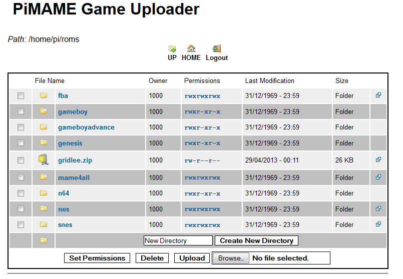
The PiMAME comes with a convenient built in web server that can be used to add ROMS. There is also a built in FTP server (recommended for files over 50 MB), for whichever is more convenient.

NOTE: All ROMs should be stored in the /home/pi/roms/ directory

To determine your IP address, you simply select "Tools" from the menu. Your IP address will be listed at the top of the "Tools" page.

Once you have the IP address, open up a browser and browse to the IP address.


Click the "ROM Uploader" button, and login. Select the "roms" folder. This is where your ROMs should go.

ROMs

PiMAME only comes with one freeware ROM by the name of 'Gridlee'.

So where does one get other game ROMs from?

Legal:
Less Legal: ("Yo Ho, Yo Ho, A Pirate's Life For Me")
Just in case you are curious, there is a very small handful of game creators that have opted to allow legal usage of their game ROMs.  Unfortunately, none of these are any of the big game developers like Nintendo, who are very actively against emulators and ROMs.

Gridlee

Let's see one of the emulators in action.  As Gridlee is the only included ROM, let's play Gridlee.  To start Gridlee, from the PiMAME menu, select "Arcade Emulators" then "AdvanceMAME".  When AdvanceMAME loads there will be only one game listed, Gridlee.  Press enter to start Gridlee.

The point of Gridlee is to move your character around and catch the bouncing balls.  There are also tall cylindrical enemies you can shoot, before they electrify the ground and hurt you.

I was a bit frustrated at first, trying to determine what they key bindings were and how to start the game.  To save you a few seconds, press "1" to start a single player game, or press "2" for a one-at-a-time two player game.  Press "5" to add coins for player 1 and press "6" to add coins for player 2.  The arrow keys will move your character around, and the "Control" key will fire your weapon.  You can press "F1" to see a list of the key options.

Maintenance

To perform updates and other tasks, I prefer to do these from a remote SSH session. As mentioned before, to determine your IP address, you can simply select "Tools" from the menu, or you can exit the PiMAME Menu and run ifconfig. Your IP address will be listed at the top of the "Tools" page.

The default user login is user "pi" with a password of "raspberry". When you connect through SSH the PiMAME menu will appear. This is due to PiMAME being set to start in the user's profile. None of the applications will run from a SSH session, so select menu option "6 - Exit" to return to the console.

Once you are in the shell, you can run the PiMAME update (or other console tasks).
# cd pimame_installer/
# sudo ./update.sh

# sudo reboot


Friday, November 29, 2013

Raspbian Wireless Wi-Fi


Are you wanting to connect to your Raspberry Pi over WiFi?  The following are instructions for configuring WiFi on Raspbian (the other Debian based Raspberry Pi distributions should work in a similar manner).

Although the Raspberry Pi model B conveniently comes with an Ethernet port (the model A does not), there are a number of applications where having WiFi is super convenient.  I have one of my Raspberry Pi out in our garage, controlling and monitoring the garage door.  Running a network cable would have been a very ugly solution.

To connect via wireless one must add a WiFi USB dongle, which will consume one of your precious few available USB ports (maybe time to expand with a powered USB hub).  There are other low level hardware options, but nothing quite as simple, and plug and play, as a WiFi USB dongle.

There are a number of compatible WiFi USB dongles on the market.  Review the RPi USB Wi-Fi Adapters list for verified adapters.  My personal favorite is the Edimax EW-7811Un 150 Mbps Wireless 11n Nano Size USB Adapter (pictured above), as it is popular, works fairly well, and is only $9 on Amazon (with Amazon Prime).

To enable WiFi, simple connect your WiFI USB dongle to an available USB port, modify your network interfaces configuration file and restart your Pi.  To configure the network interfaces configuration file, add the wlan0 section to /etc/network/interfaces:
auto lo
iface lo inet loopback

iface eth0 inet dhcp

auto wlan0
allow-hotplug wlan0
iface wlan0 inet dhcp
        wpa-ssid "YOUR_SSID"
        wpa-psk "YOUR_WEP_OR_WPA_KEY"
wpa-conf /etc/wpa_supplicant/wpa_supplicant.conf

iface default inet dhcp

Your WPA key above can specified as either be the clear text passphrase, or the hex encoded version.  If you would prefer to not list your clear text passphrase you can generate the encoded hex version with the wpa_passphrase tool or even online tools.
# wpa_passphrase test testtesttest
network={
        ssid="test"
        #psk="testtesttest"
        psk=b6df3a2ab8a19db1b646e4a852892d39fc4e73c13cb2ade0ad9d8887bb414ecd
}

WPA passwords are managed on Linux with the wpa_supplicant tools.  The wpa_passphrase tool is designed to generate a section that can be added to the /etc/wpa_supplicant/wpa_supplicant.conf configuration file.  You can also add multiple SSIDs to wpa_supplicant.conf.  If you have multiple SSID you may want to connect to (such as a mobile Raspberry Pi), don't add the wpa-ssid and wpa-psk lines to the interfaces file.  Instead use the wpa_passphrase tool to add multiple sections to the wpa_supplicant.conf configuration file.

You can auto add the output of wpa_passphrase, to the wpa_supplicant.conf, with the following:
# wpa_passphrase test testtesttest >> /etc/wpa_supplicant/wpa_supplicant.conf

Finally, to bring up the wireless, either reboot the Raspberry Pi, or run the following:
# ifdown wlan0
# ifup wlan0

You should now be able to use your Raspberry Pi over WiFi.


For reference, there are several command line tools that can be used to manually configure and view wireless settings.

To see your wireless IP address:
# ifconfig wlan0
lan0     Link encap:Ethernet  HWaddr 80:1f:02:be:XX:Xx
          inet addr:10.10.10.100  Bcast:10.10.10.255  Mask:255.255.255.0

To manually configure SSID and other wireless options, the iwconfig command can be used. The output of iwconfig looks similar to the ifwconfig, but with wireless settings:
# iwconfig wlan0
wlan0     IEEE 802.11bg  ESSID:"MY_SSID"  Nickname:""
          Mode:Managed  Frequency:2.437 GHz  Access Point: 00:14:BF:E0:XX:XX
          Bit Rate:54 Mb/s   Sensitivity:0/0
          Encryption key:****-****-****-****-****-****-****-****   Security mode:open

To scan for wireless access points:
# iwlist wlan0 scan
wlan0     Scan completed :
          Cell 01 - Address: 00:14:BF:E0:89:XX
                    ESSID:"MY_SSID"
                    Protocol:IEEE 802.11bg
                    Mode:Master
                    Frequency:2.437 GHz (Channel 6)
                    Encryption key:on
                    Bit Rates:54 Mb/s